Getting the Direction Right from the Start
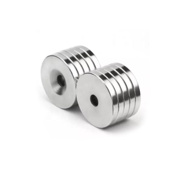
Let's be straight with each other—when you're hunting down **neodymium-ring-magnets** for that new motor prototype or precision sensing rig, it's awfully easy to obsess over the N-grade or the OD tolerance. I've done it myself. But after a decade in this business, I'll tell you what separates a design that sings from one that stumbles: magnetization direction. Miss this one spec, and you're not just looking at subpar performance—you're building a component that fundamentally fights your mechanical layout. That axially magnetized ring crammed into a radial air gap? Yeah, I've watched that disaster unfold on a dyno. Sounded like rocks in a blender.
Here's the thing people gloss over: this choice isn't just technical trivia. It's a strategic fork in the road. Axial or radial magnetization shapes the soul of your magnetic circuit—through the thickness or across the diameter—and that single call ripples through your housing design, your assembly tolerances, and ultimately your bill of materials.
What Is Magnetization Direction in Ring Magnets?
Before we get into the weeds, let's talk about what's actually happening inside that hunk of sintered material.
How Neodymium Magnets Are Magnetized
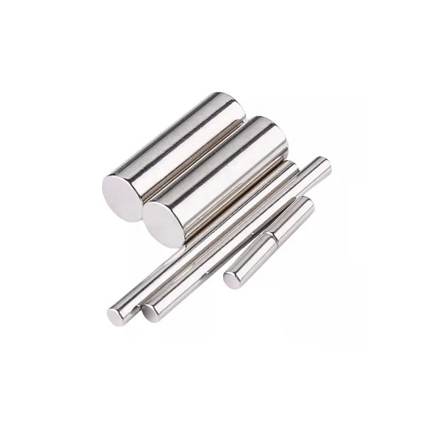
Those neodymium rings you're holding start as "green" blanks—dense little pucks with all the magnetic personality of a paperweight. We hit them with a pulse field that'd fry your phone from ten feet away. That pulse aligns the magnetic domains. For sintered material, that alignment follows an axis baked in during the pressing stage. You can't change it later without starting over.
Why Magnetization Direction Matters in Assemblies
Pick a direction, and you've locked in three things:
- **Magnetic Field Distribution:** Where the flux actually concentrates when you put the thing to work.
- **Assembly Performance:** How that ring plays with Hall sensors, iron cores, or opposing poles in your stack-up.
- **System Design:** Whether you need external flux guides or can run open-loop.
Nail the direction, and your efficiency numbers look good. Miss it, and you're fighting the physics all the way to the scrap bin.
Axial Magnetization in Ring Magnets
What Axial Magnetization Means
Picture a washer on your workbench. Axial magnetization means the top face is North, the bottom face is South. Simple as that. The field punches straight through the thickness.
Typical Applications of Axial Ring Magnets
This is your bread-and-butter configuration for holding applications. Nothing fancy, just solid performance. In production environments, I've spotted axial rings doing heavy lifting in:
- **Proximity Sensors and Reed Switches:** That face-projected field trips the sensor clean and fast.
- **Magnetic Couplings:** Torque transfers through a stainless barrier via face-to-face pull.
- **Holding Assemblies:** Workholding fixtures where you need a ferrous plate stuck to a surface.
Advantages of Axial Magnetization
**Easier Manufacturing:** The tooling guys don't break a sweat over this. Magnetization fixtures are catalog items. - Availability: Standard stuff means shorter lead times and friendlier pricing. Good for production scheduling.
Radial Magnetization in Ring Magnets
What Radial Magnetization Means
This is where the conversation gets interesting—and where rookie mistakes happen. A radially magnetized ring carries its poles on the inner diameter and outer diameter. Usually, one diameter is North, the other South. The field crosses the wall thickness, traveling from ID to OD.
Applications of Radial Magnetized Ring Magnets
If your assembly spins, you probably need radial. These rings are the unsung heroes of rotary motion:
- **Brushless DC Motors (BLDC):** That field radiating outward engages the stator windings where it counts.
- **Magnetic Encoders:** A radial ring spinning on a shaft throws a clean field variation that sensors lock onto for position feedback.
- **Rotating Assemblies:** Any rig where magnetic action happens around the circumference rather than off the ends.
Manufacturing Complexity of Radial Magnetization
Learned this one the hard way with a batch of encoder rings that flunked QC. Radial magnetization demands specialized fixtures. You're arranging coils to push that field through the diameter—not a simple axial shove. That complexity means longer lead times and steeper tooling charges, especially when you're prototyping.
Multi-Pole Magnetization in Ring Magnets
What Multi-Pole Magnetization Is
Axial and radial describe direction. Multi-pole describes pattern. Instead of one North and one South, you're looking at alternating poles—N-S-N-S—marching around the circumference. You can apply this to axial or radial blanks, but radial multi-pole is the gold standard when motion control enters the chat.
Typical Applications
- **Magnetic Encoders:** High-res speed and position sensing that won't drift.
- **Servo Motors:** That buttery smooth rotation automation guys chase.
- **Automotive Sensors:** Cam and crank position sensing where failure isn't an option.
Choosing the Correct Magnetization for Your Application
Assembly Structure Considerations
Ask yourself one question: where's the air gap? If magnetic interaction happens across the face—pulling a plate toward the magnet—axial is your play. If it happens around the circumference—inside a motor stator—you need radial. Overthink this and you'll underdeliver.
Magnetic Field Requirements
Guessing gets expensive. We run FEA simulations on every custom job now. An axial field bleeds off the ring corners. A radial field concentrates in that ID-OD air gap where you actually need it.
Engineering Consultation with Manufacturers
When we talk **custom-neodymium-magnet** projects, this is where the rubber meets the road. A solid manufacturer doesn't just ask "What's the OD?" They dig deeper: "Where are your poles landing?" If that question never comes up during quoting, walk. Plenty of shops out there happy to take your money and ship you disappointment.
Manufacturing Custom Magnetization for Ring Magnets
The Build-to-Print Logic
For production volumes, magnetization direction gets locked in the engineering drawings. Non-negotiable. We run Build-to-Print:
1. **Customer Drawings:** Your CAD and spec sheet drive the train.
2. **Confirmed Magnetization Direction:** Drawing explicitly states "AXIAL" or "RADIAL"—pole count too if you're going multi-pole.
3. **Production Based on Specifications:** We stand up custom magnetizing fixtures matched to your prints.
A Note on Disc Magnets
Worth mentioning that **neodymium-disc-magnets** play by similar rules. Most folks assume discs are always axially magnetized—poles on the flat ends. That's the default, sure. But diametric magnetization exists too. In that config, poles live on the curved sides. It's the disc equivalent of radial. If your sensor rig needs a field running across the diameter for some niche application, that option's absolutely available. We've built them.
Real Talk: Making the Final Call
Look, after years watching good engineers chase bad specs, here's my take: don't marry the magnet grade before you've confirmed direction. I've watched N52 rings flop hard in motors because someone assumed axial would work in a radial stator. Meanwhile, a lower-grade radial ring outperformed everyone's projections because the flux actually went where the design needed it.
If you're ordering thousands of units, prototype with the correct magnetization. Test field distribution under load. And for heaven's sake, make sure your supplier knows the difference between throwing a field through the hole versus throwing it around the hole. Your production line—and your customers—will thank you when the first article passes validation without drama.
Your Custom Neodymium Magnets Project
We can offer the OEM/ODM services of our products. The product can be customized according to your personalized requirements, including the size, Shape, performance, and coating. please offer your design documents or tell us your ideas and our R&D team will do the rest.
Other Types of Magnets


Post time: Mar-20-2026